Blackadders WIP Warlord Titan

  • The masquerade of murder returns! A new game of Vampires Amongst Us has begun. Unmask the killers, trust no one, and try to survive the night. Find out more and sign up now!

The_Blackadder

Vargheist
Dec 7, 2010
637
Zombies
594
Okay so here's the deal, I photo-shopped the image and made a static front view that prints out a model exactly 24 inches tall (On my printer using my editor's print graph I hasten to add). I'm satisfied that this is viable height for a Warlord towering almost 2.5 times the height of a Warhound.

This is the goal:

View attachment ai.imgur.com_BktwNl.jpg
http://i.imgur.com/BktwN.jpg

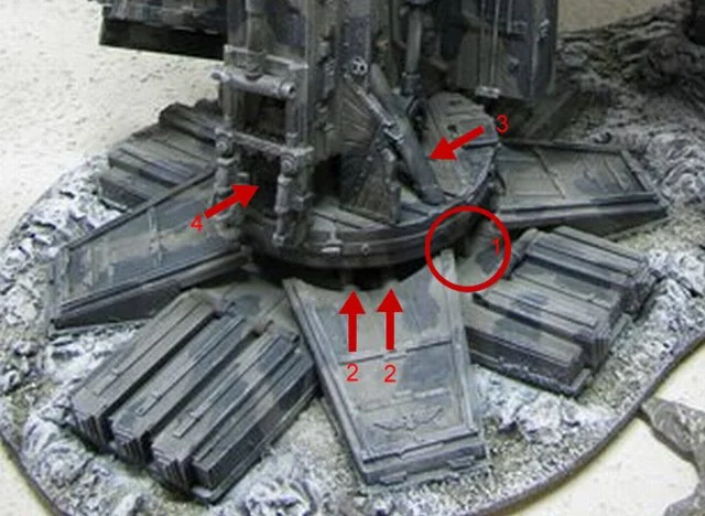
The most fantastic Warlord I have ever seen:
View attachment ai.imgur.com_jxSKol.jpg
http://i.imgur.com/jxSKo.jpg

View attachment ai.imgur.com_xN08Bl.jpg
http://i.imgur.com/xN08B.jpg

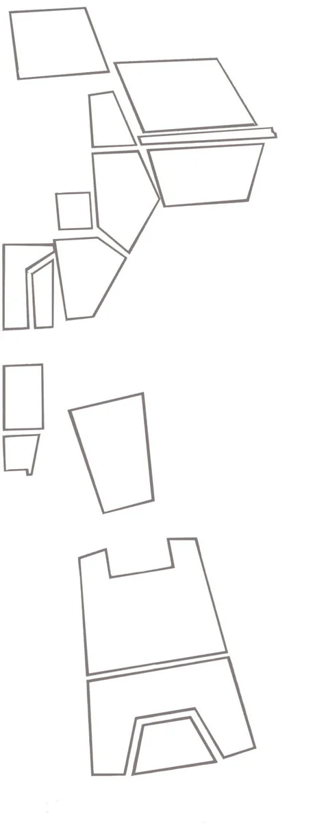
Now that I have the overall height I'll remove the armour and draw in the structural detail.

BTW that's 24 inches to the lower margin of the image because we mustn't forget the foot pads.

ai.imgur.com_xiYya.webp


I calculate the center disk of the foot to be about 3.625 inches in diameter.
 
I know I'm gonna reap a lot of flack for ignoring the T'hawk but I'm on a roll with this project and will ride it for all it's worth.

This new enthusiasm is refreshing as working on the T'hawk was becoming tedious but already I'm looking at it with fresh ideas

The toes of Chrysagon coming along nicely an if I have to make the body a few inches taller so be it.

ai.imgur.com_6o0pkl.webp

http://i.imgur.com/6o0pk.jpg

ai.imgur.com_qVyZGl.webp

http://i.imgur.com/qVyZG.jpg

ai.imgur.com_0mXpPl.webp

http://i.imgur.com/0mXpP.jpg

Hey isn't there any way to get a black letters on a white background on this forum? My tired old eyes find it difficult to read white letters on black. And red letters forgeddabouddit!
 
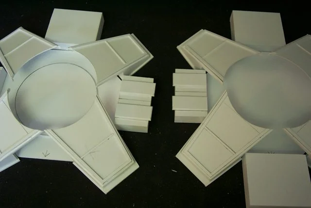
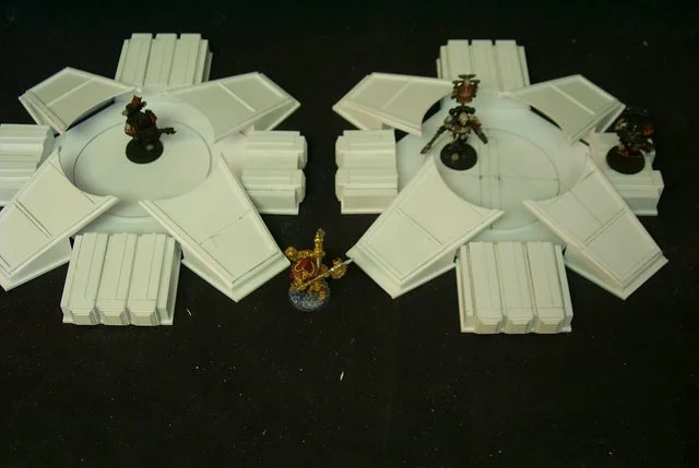
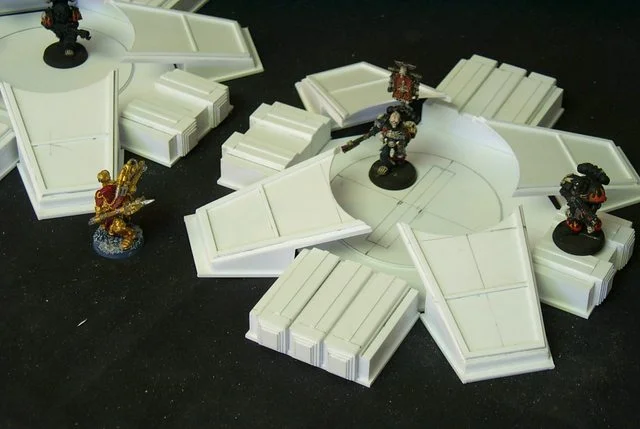
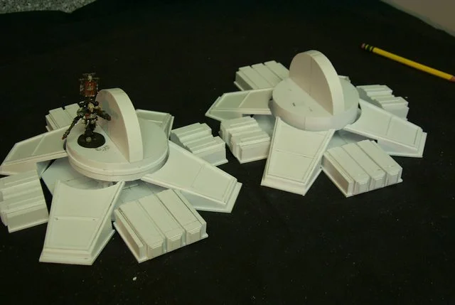
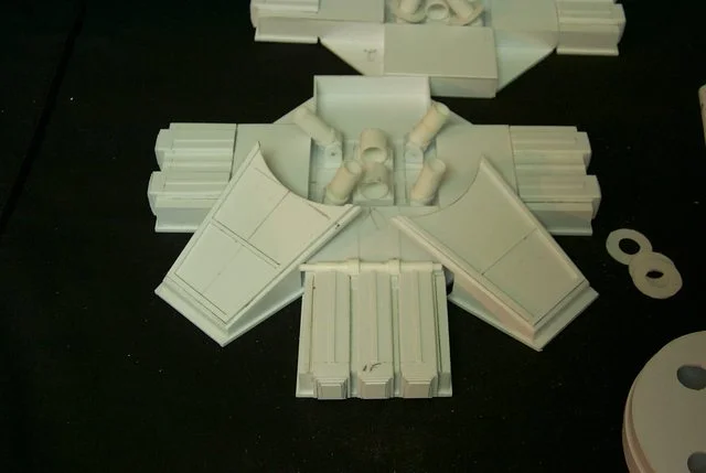
Plodding along as is my wont I successfully attached the step pyramid style ends of the toes this morning which for the life of me serve no earthly purpose other than aesthetic appeal. (If you like toes.... Jabba )

Mine differ from DS's in that they are slightly wider but the overall design is the same.

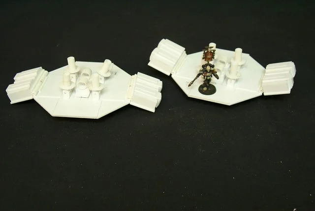
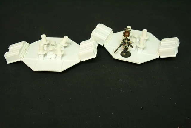
Accompanying the feet are some figures to convey scale donated by my son.

http://i.imgur.com/fJVPu.jpg
ai.imgur.com_fJVPul.webp


http://i.imgur.com/r5yJw.jpg
ai.imgur.com_r5yJwl.webp
 
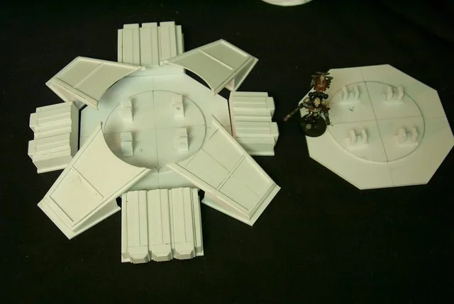
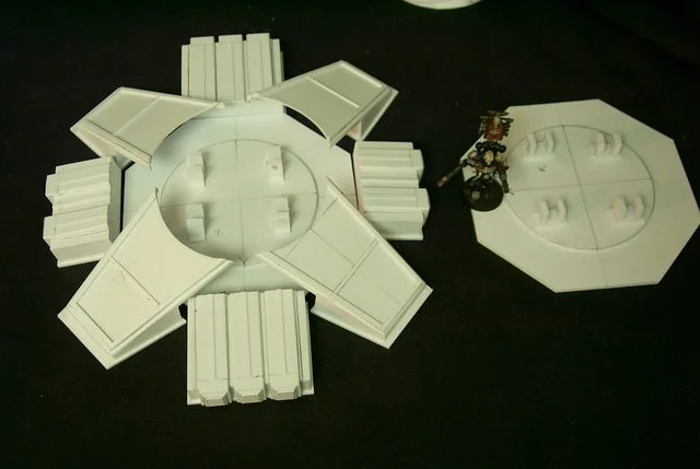
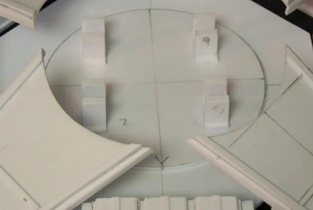
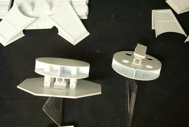
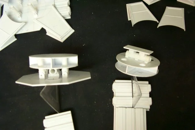
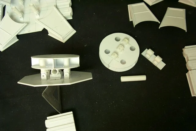
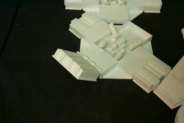
A bit further along on the disc mount mechanism placed but not glued are the rough cylinder trunnion mount blocks which are in essence pairs of pillow block bearings. Not glued because I don't know how much distance I need for the cylinder travel and still allow the disc plate a full range of tilt. mebbe I should do a drawing.

http://i.imgur.com/DZPp9.jpg
ai.imgur.com_DZPp9l.webp


http://i.imgur.com/YJ5Zb.jpg
ai.imgur.com_YJ5Zbl.webp


http://i.imgur.com/IeSOI.jpg
ai.imgur.com_IeSOIl.webp
 
I've been working on the disc tilting cylinders. These will allow the disc to tilt side to side while secured to a longitudinal pivot axle yet to be fabricated.

http://i.imgur.com/DZPp9.jpg
ai.imgur.com_DZPp9l.webp


http://i.imgur.com/YJ5Zb.jpg
ai.imgur.com_YJ5Zbl.webp


http://i.imgur.com/IeSOI.jpg
ai.imgur.com_IeSOIl.webp


http://i.imgur.com/NopdI.jpg
ai.imgur.com_NopdIl.webp


http://i.imgur.com/orHOg.jpg
ai.imgur.com_orHOgl.webp
 
It's extremely gratifying to envision something in your mind's eye and then to duplicate it in some medium. In this case extremely malleable styrene but I can see how real engineers get their rocks off. Granted the days of Isambard Kingdom Brunel and John Scott Russell are pretty much over where an engineer designs and executes an entire construct but I'm sure even today such gratification must still exist.

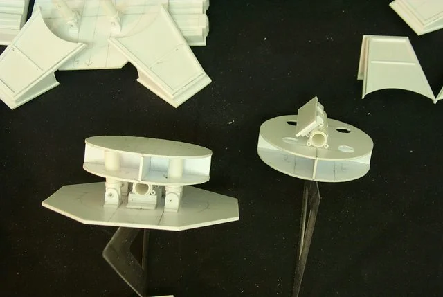
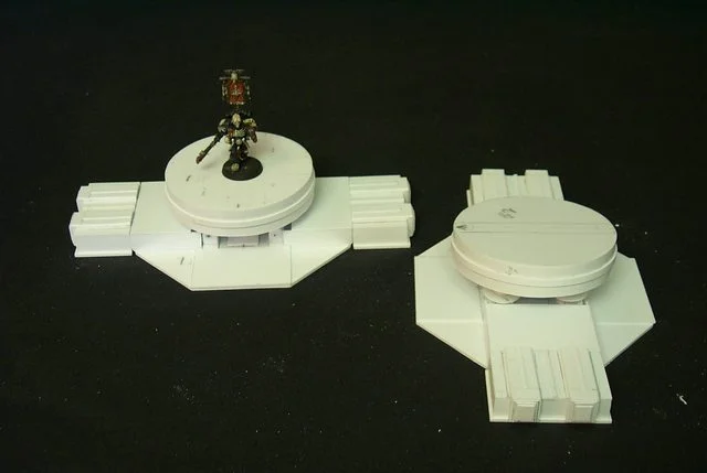
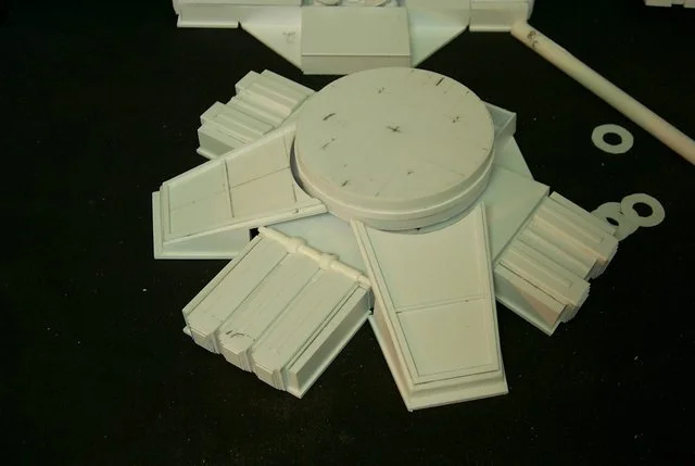
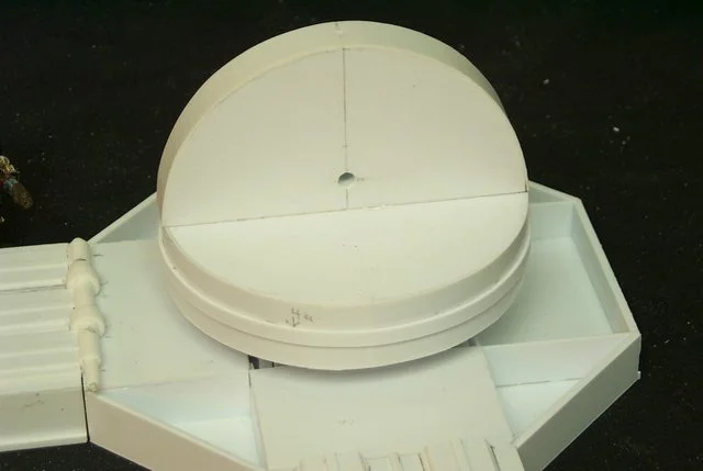
Case in point, this highly speculative tilting table mechanism for the foot attachment.

I believe I have come up with a viable solution to allow the foot to tilt side to side, be light and strong and also look complex enough to grace a 40K denizen.
http://i.imgur.com/k07P5.jpg
ai.imgur.com_k07P5l.webp


Were I to build this for a real vehicle I would enclose the axle within the disc housing so the table doesn't shift side to side as much but then the mechanism would be totally hidden. so this way I have an excuse for the diagonal toes linear actuator system that give enhanced stability during the stepping process and decreases the upper body swaying which is the cause of so much seasickness in some Warhound crew members.
http://i.imgur.com/adYW2.jpg
ai.imgur.com_adYW2l.webp


That's my story and I stick with it :P
http://i.imgur.com/X81v7.jpg
ai.imgur.com_X81v7l.webp


When I see how much of this system will actually be visible I may fancy it up a bit using some of mxwllmdr's lightened girder and buttress techniques.

The beauty of this construct is it can be disassembled for maintenance, painting and repair.
http://i.imgur.com/jScLR.jpg
ai.imgur.com_jScLRl.webp
 
Faaantastic! This is seriously so cool. I will be watching this for as long as it continues!
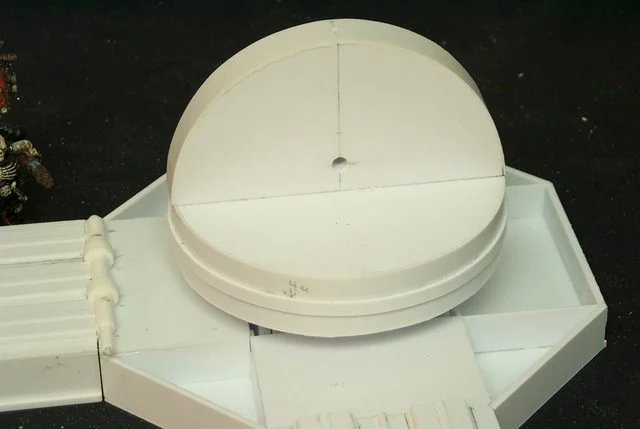
So the discs will be loosely attached to the feet to allow them be picked apart as well as tilt?
 
Tarkas said:
Faaantastic! This is seriously so cool. I will be watching this for as long as it continues!

So the discs will be loosely attached to the feet to allow them be picked apart as well as tilt?

The foot pads will be securely attached with reinforced 7/16 inch tubing that as it is right now will bear me pressing down on the unreinforced disc and axle assembly with a force in excess of twenty pounds so both discs will support 30 to 40 pounds which I calculate exceeds three times the completed model weight.

Chaos_Born said:
What are you making it out of, if you don't mind me asking.

To answer the above question I am using almost exclusively Evergreen styrene plasticard.
 
Back to business:

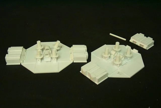
Before I close up the workings of the feet perhaps a demo of the hinges I came up with to allow the side toes to flex.

At this point they can flex up and down but once the box like hydraulic compartments at the base of the toes are installed upward movement will be restricted.

http://i.imgur.com/HyfxP.jpg
ai.imgur.com_HyfxPl.webp


http://i.imgur.com/vSWL8.jpg
ai.imgur.com_vSWL8l.webp


http://i.imgur.com/aLFwT.jpg
ai.imgur.com_aLFwTl.webp
 
Anyway it's the weekend baby and I'm hot modeling-wise I hope to have the front and rear toes mounted today.

http://i.imgur.com/yixnd.jpg
ai.imgur.com_yixndl.webp


231
 
Well the weekend is over and in a flurry of productiveness I managed to attach one front toe With hinge as planned and it works and seems relatively strong

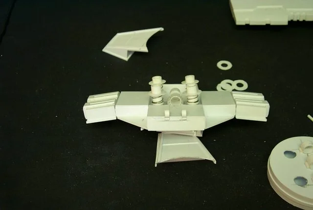
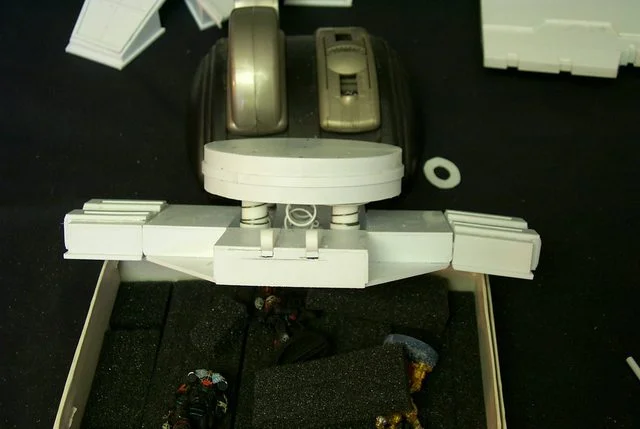
Now the diagonal stabilizers need a bit of work but nothing extraordinary and they do allow the foot to flex so there's no cause for concern. I can't mount the back toes yet as I have to find 3/8 dia light springs to stabilize the disc; much better than my piston cylinder design, a suggestion from Zathros, a Moderator on another forum and to whom I say thanks.

http://i.imgur.com/ykY34.jpg
ai.imgur.com_ykY34l.webp


http://i.imgur.com/2oPzF.jpg
ai.imgur.com_2oPzFl.webp


http://i.imgur.com/mbET8.jpg
ai.imgur.com_mbET8l.webp


http://i.imgur.com/6Lguf.jpg
ai.imgur.com_6Lgufl.webp
 
I found some 1/2 inch springs 1 inch tall and set about modifying the disc stabilizing system to accept them. I have to admit it works rather well.

http://i.imgur.com/5948k.jpg
ai.imgur.com_5948kl.webp


http://i.imgur.com/jXNRj.jpg
ai.imgur.com_jXNRjl.webp
 
But it does look sooo good!

I find this project kinda jaw-dropping and very inspiring. I will continue following you on this to 100% and support the project all the way! Keep them regular updates coming once in a while like you have. From a personal perspective I think it's great fun and easy to follow since I'm not the most active one around. xD

Your project so far is and looks really cool! :happy:
 
Alas motorizing is out of the question due to the softness of the material. The moving parts are just for display and to test the limits of the medium

The fact that this project inspires is all that I can hope for. It is gratifying to build with this material and I enjoy stimulating others to try.

With the paranoia of machine shop precision I managed to drill and tap two perfect (with apologies to Werner Heisenberg) holes with a 10-32 tap for my axle shafts. Tack glue them in place and set aside to dry and for photos.

http://i.imgur.com/kGPog.jpg
ai.imgur.com_kGPogl.webp


http://i.imgur.com/eqVE9.jpg
ai.imgur.com_eqVE9l.webp


http://i.imgur.com/v42fz.jpg
ai.imgur.com_v42fzl.webp
 
Shot in the dark.......but when your done can you send me the blue prints...? My brother has a metal mill and lathe downstairs.......*insert cackling here*

Anyhow looks awesome man! way to make my over kill seem small D:
 
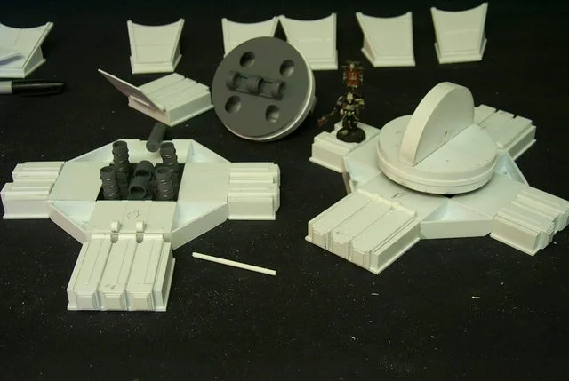
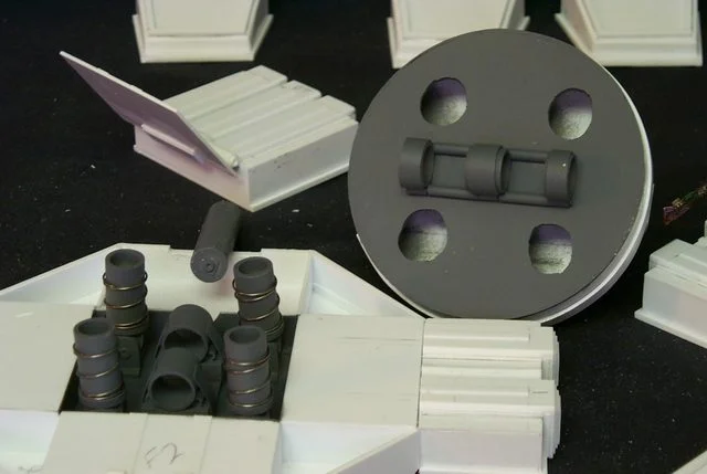
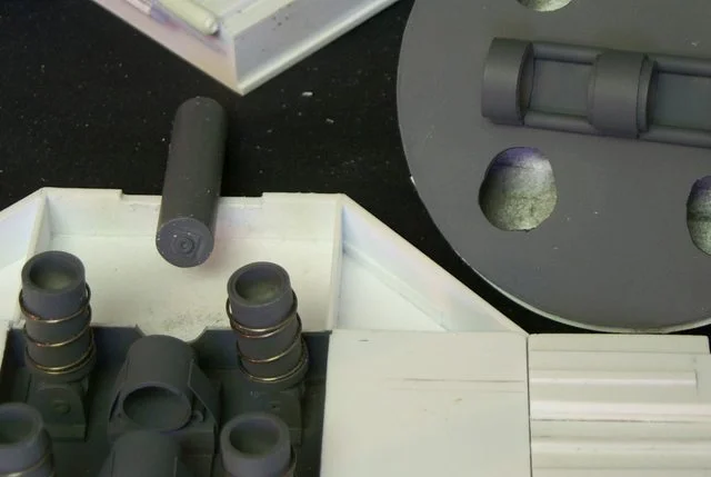
I pulled a virtual all nighter and managed to apply a bit of colour (gray is a colour) to the mechanical interior of the foot before final assembly. once the rear toe compartment is glued on it will require micro surgery to access the stabilizer components. I did a lot of reinforcing before I sealed it up. Its a good thing I took pictures because painted gray not much of the mechanics is visible.

http://i.imgur.com/7ez94.jpg
ai.imgur.com_7ez94l.webp


http://i.imgur.com/7W8iG.jpg
ai.imgur.com_7W8iGl.webp


http://i.imgur.com/jYBJE.jpg
ai.imgur.com_jYBJEl.webp


http://i.imgur.com/NzKR9.jpg
ai.imgur.com_NzKR9l.webp
 

About us

  • Our community has been around for many years and pride ourselves on offering unbiased, critical discussion among people of all different backgrounds. We are working every day to make sure our community is one of the best.

Quick Navigation

User Menu