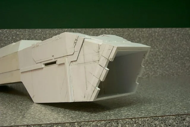
Scratchbuilt Thunderhawk

  • The masquerade of murder returns! A new game of Vampires Amongst Us has begun. Unmask the killers, trust no one, and try to survive the night. Find out more and sign up now!
Or maybe the middle one has an internal intake that sucks all the cabin oxygen into it, hence killing anyone who isnt a space marine via oxygen starvation?
lol kidding...
 
No air in space! How is that X wings and Tie fighters howl and whoosh when they do a flyby. Just kidding but speaking of planning ahead:

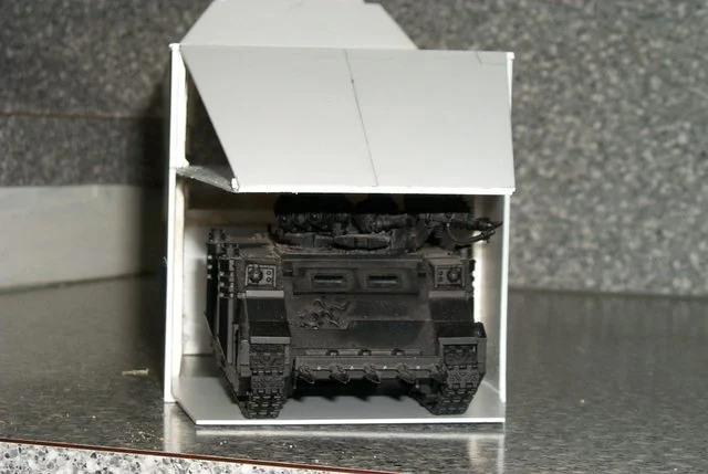
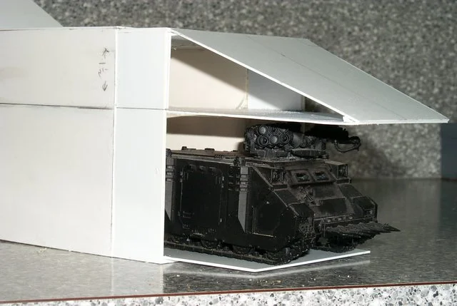
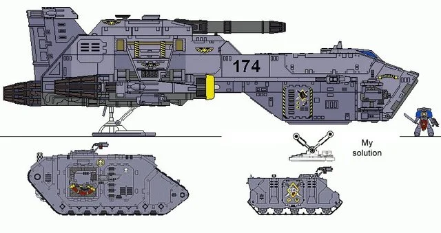
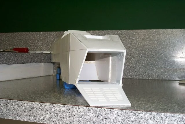
I hope this next post doesn't put you off. A while back possibly not on this forum I asked if a T'hawk could transport a Rhino in it's cargo bay and was told no a special transport T'hawk slings them under the belly. Well I didn't mention it before I had conformation and I guestimated the size required to fit a Rhino and as my son is home from college for the Summer I borrowed one of his. Guess what! room to spare and I mightn't need to make the front doors clamshell as in the C5A. I stand before you ready to suffer your slings and arrows for this, The Blackadder's 'Super Thunderhawk'

ai.imgur.com_ueBJol.webp

ai.imgur.com_P4dMxl.webp

ai.imgur.com_AL7Sal.webp
 
will you still add the couplings for either the 2 rhinos or a land raider that the thunderhawk can carry? and thats some convienient spacing :P
 
I'm going to stick with the cargo bay cockpit and under the air brake flaps. That should be sufficient. I know there is a wealth of detail in the FW kit, (They should invest some of that energy in making their moulds stable.) but what I have seen in most of the resin kits I've rescued is that the hatches are glued shut, the doors are inoperable and if there is a panel that can be removed to veiw some internal component it is invariably cemented in place for eternity.

Not so with the Jumbo 'hawk; the interior is coming along nicely but is a chore. Sometimes I wonder why I start these things, they monopolize a lot of time plus I ran out of crucial styrene for the floor ribs and had to make a hobby shop run this morning. I thought I'd never find a use for this size strip but I ran out two strips short of finishing and had to buy more. Now I have more than when I started. (Poor baby Blackadder.)

Any way the floor is done and the side panels are clamped in place but I won't be gluing just yet because I still haven't figured out where the landing gear cylinder goes when the nose gear is retracted. Someone's in for a bit of a shock when that nose gear bursts thru the cargo compartment floor (All together now, "Poor engineering planning FW, nowheres near as well thought out as the Warhound. And where are the actuators for the forward cargo hatch/ramp?) All these problems will have to be addressed before the interior detail can be affixed

Here's the result of a mis-spent Saturday morning:

ai.imgur.com_8IDONl.webp

ai.imgur.com_oiLVwl.webp

ai.imgur.com_oiLVwl.webp
 
Designing a viable landing gear was paramount on my mind for the past weekend until I saw this video.

http://www.youtube.com/watch?v=L7u8_r07-3s&feature=youtu.be

On further watching the video I see that both forward and back actuators pivot on both ends and double as hydraulic cylinders to extend the pad and shock struts (No small feat of engineering that!) but when the strut is full extended down the front and rear cylinders become shock struts and are able to compress and absorb the landing shock.

And very little room is taken up when fully retracted.

Below is my interpretation of the landing gear mechanism:

ai.imgur.com_4tCy5l.webp

My solution to the landing gear dilemma:

ai.imgur.com_vL2fcl.webp

This model should be much simpler than the Warhound. Not having to design positionable joints strong enough to take the movement but still be the proper size so as not to look ungainly was extremely difficult with Lucie and took a lot of time. I had to rebuild the joints a few times until they were satisfactory. This retractable landing gear problem was a much easier nut to crack once I saw the scissor mechanism displayed in the video. My problem was not thinking outside the box. A background in aircraft experience would not allow me to think of an dual oleo strut/hydraulic cylinder combination (I still question the feasibility of such an appliance?) but the manufacture should be child's play compared to Lucie's toe joints; I still have nightmares about those. #-o. I may use a spring mechanism and trigger lock to deploy the gear so they do not collapse when sitting on them and not have to be pried out of the wheel well each time they are to be lowered. I'm thinking ball point pen springs should be sufficient. Once I get the proportions right on this beastie it will be a simple matter of gluing on all the fabulous detail exhibited in those 3D drawings above.
 
This will be a daft question I'm sure but are you an engineer by trade? I'm looking forward to seeing how you tackle this problem. The thing I really enjoyed about the Titan, and I'm sure it'll be the same here, is that your models go far beyond being just models!

Keep up the good work!

u_m
 
Sanai said:
Or maybe the middle one has an internal intake that sucks all the cabin oxygen into it, hence killing anyone who isnt a space marine via oxygen starvation?
lol kidding...

This would be useful if the Thunderhawk has been assigned to Space Marines. I mean, you wouldn't need to put an alarm on it when it's parked or anything. If anyone tries to steal it, they'll die mid-flight. :rofl2:

Unless CSM steal it, but then they've got their own aircraft anyway... ;)

The Thunderhawk's looking neat. I want to see MOAR!
 
Sorry for the delayed reply, I wasn't notified of a response,

No not an engineer, an engineer could tackle these problems without a second thought.

As you can see my vision of the Thunderhawk is slightly larger than the FW offering. My first impression of the Thunderhawk concept was that it be capable of carrying a Rhino. After all for what else would be the purpose of such a huge loading door? Imagine my disappointment when I found the FW Thunderhawk too diminutive to disgorge even so small a tank as a Rhino. I am still mulling over the necessity of hinging the forward side panels to allow more clearance; hell I probably shall in the end not being satisfied with compromising measures. Image the dramatic effect when your Thunderhawk glides to a touchdown, the ramp drops, the side doors open, and it vomits forth an APC.

ai.imgur.com_wZcIsl.webp

ai.imgur.com_LC6ytl.webp

Sweet!
 
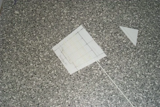
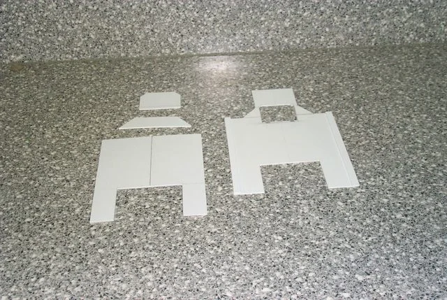
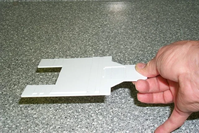
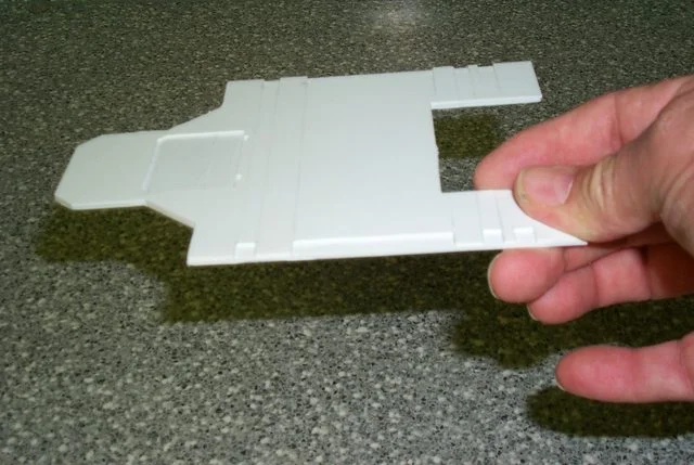
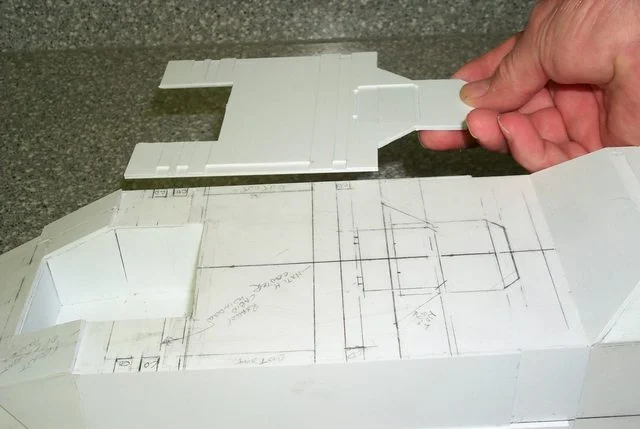
Starting on the ramp because I need to install the hinge tube before I can apply the nose armour. Below is a practical demonstration of how to make ribbed flooring.

ai.imgur.com_gnYASl.webp

ai.imgur.com_ubVHDl.webp

ai.imgur.com_YXl0ul.webp
 
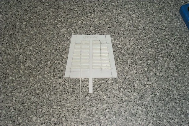
Part of the fun of scratchbuilding (If you have a penchant for masochism that is.) is inventing ways to replicate in stock styrene the intricacies of injection mould plastic kits etc. There were two ways to approach the manufacture of the object below. One was to attempt to cut the slots in a single piece of sheet plastic and glue it onto a backing. I rejected that straight out because the finished product regardless of the care exercised would be crude and amateurish. The second, the option I chose was to build the corrugations one slat at a time as demonstrated in the previous reply, score the perpendicular channels with a sharp utility knife, widen and deepen the score with a razor saw, and shave out the residue with a chisel bladed Exacto knife. This worked well for the wide center longitudinal reinforcement but how to make the narrow side reinforcements? Start as before with the score and the razor saw to accomplish the primary cut. Then taking your razor saw at a 45° angle carefully widen the score to the required width. If you have jewelers files you can dress the sides of the channels but in this case it was not necessary.

Now I'll see if I can repeat the process on the other side without screwing the damned thing up.

ai.imgur.com_tdnTil.webp

Then taking your razor saw at a 45° angle carefully widen the score to the required width. If you have jewelers files you can dress the sides of the channels but in this case it was not necessary.

Pictured below are the only tools necessary to accomplish this exercise . Had I to do this over again I would have angled the side channels slightly out at the bottom to dispel the illusion that they converge.

ai.imgur.com_ykj53l.webp
 
The purpose of the forward door is to disgorge terminator squads and dreadnaughts with ease in battle.
For carrying vehicles they have this baby...
awww.forgeworld.co.uk_Images_Product_AlternativeFW_large_Thawkrhino2.webp


But of course, many space marine chapters (and I suppose inquisitors with access to the right facilities/tech priests) do modify vehicles and create their own patterns of various vehicles, so the thunderhawk could be your own pattern.
 
Sanai said:
The purpose of the forward door is to disgorge terminator squads and dreadnaughts with ease in battle.

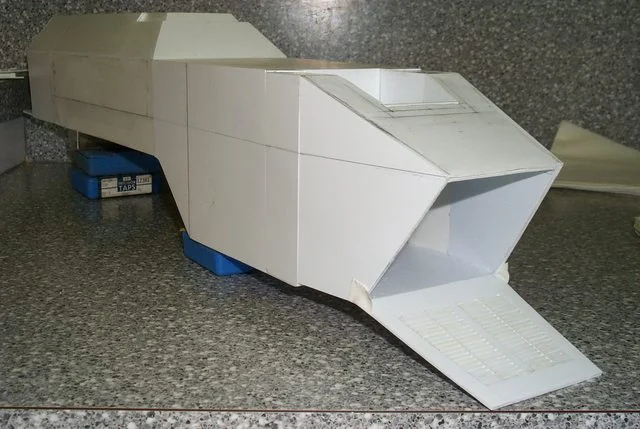
I am well aware of the primary role of the Thunderhawk but the exergy of battle frequently places excessive demands on equipment. From firsthand experience I know that military vehicles sometimes are needed to be employed in roles that for which they were not intended. All hardware is expendable and secondary to the objective. If the capacity to carry outsized loads is there it will carry outsized loads! 'nuff said.

Besides I defy the regulation FW Thunderhawk to have the capacity to actually house a full blown Dreadnought which I am apprised stands in excess of 60 MM :D

Considering it took the better part of a week just to make the loading ramp fruition will be a long time coming. In my defense my workload this week was extremely heavy and I could only devote a half hour in the morning to working on the ramp. The slats had to be secure before the next could be applied or they would move when the spacer was run between them. I also managed to apply the outer skin (1 MM sheet styrene) to the forward hull. I finished up the ramp this morning and taped it into place. Everything is square and true so tomorrow I will start applying the forward armour. This will be the fun part when the model starts to look like something other than a long white shoebox. Right now I am sitting back sipping a well deserved Martini and reflecting on a satisfactory accomplishment.

ai.imgur.com_3hxpjl.webp

ai.imgur.com_tmSrxl.webp

My patience is holding strong and the worst of the build is behind me now it's just a matter of detail, the part I relish.
 
Right now I'm gluing on the second layer of sheathing to strengthen the hull and provide a good base for the armour.

ai.imgur.com_o4jBGl.webp

ai.imgur.com_t4srJl.webp

ai.imgur.com_4gTFKl.webp

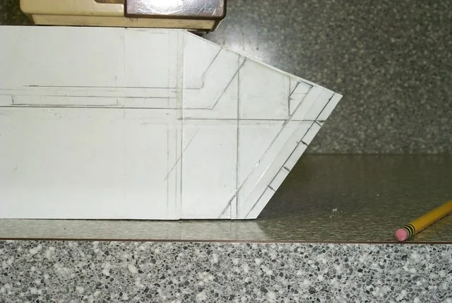
Not really much to see for all the work involved but as a matter of interest the hull is square and true to the width of a sharpened pencil line in cross section and in length. Speaking of length I may have gone overboard in extending the aft hull I'll have to see after the forward armour is installed. I'm trying to avoid the blocky look of the FW model but right now I feel it may be a decimeter too long.
 
Whew, after a month of convalescing I'm back and finally feel like building models again. I don't recommend spending three weeks in a hospital.

Anyhow here is my first days labor on my long neglected project. I've decided to install the armour as I proceed back to the unfinished stern section. This is probably a mistake but I believe the hull is too long so once the armour in the front is done I'll be better able to trust my eye than actual measurements. As per usual I shall be doing this the hard way. No wonder I have ulcers.

ai.imgur.com_srXdCl.webp

I've laid out the coordinating lines on the hull and am fashioning the armour to fit. This is why it would be prohibitive to duplicate and sell copies of this model aside from copyright infringments

ai.imgur.com_DfBukl.webp

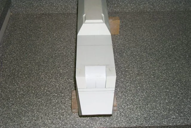
Front view more of the same. The hull walls are approaching the proper thickness now.

ai.imgur.com_DfBukl.webp

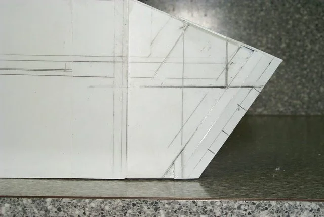
Side view of the nose armour which I calcuate to be 1.5 MM thick.
 
Whoops big errors, have to re-do the nose armour. Not up to my usual form as yet but fortunately I caught the errors before I went too far.

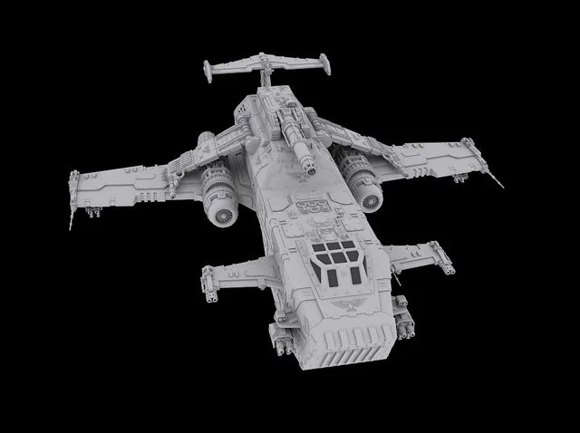
Strangely I had forgotten I made this enlarged image on my photo editor to plot coordinating intersections. The actual model superimposes rather well on the 3D image with the exception of the most recent work which will be rectified. It appears that 6.0 mm is the proper thickness for the front cargo door and the aligning recesses in the side armour. The image has a two pixel margin of error due to the fuzziness of the enlargement. I can live with that.

ai.imgur.com_nqdIHl.webp

Rather poor planned out in my estimation.

ai.imgur.com_SvWMEl.webp

This is the goal.

ai.imgur.com_QGHdtl.webp

With coordination lines superimposed on model

ai.imgur.com_r11Jcl.webp

With pencil lines adjusted on model; by god that is close enough for government work.

E. Blackadder
 
Blackadder, your level of patience, dedication and the effort you put into your plans amazes me so! When can we expect to see the finished product eh? ;P
 
Lucie was pretty much built when I posted her on this forum and she took a year and a half to build I'm hoping this will take a lot less time.

I was wondering how to do the intricate double layered top of the hull armour without a seam in the finished skin. Part of the beauty of the 3D rendering is that seamless broad expanse of armour with all the cutouts in the edge and compound angles and vent fan cutout, set. Cutting this piece out of 2.5 mm styrene would be very difficult to get perfectly straight cuts and 90° vertical edges.

ai.imgur.com_a7BvUl.webp

My solution (if it works) is to make the substrate of 1.5 mm sheeting with 6.3 X 1.5 mm edging strips using all together 5 pieces and then after all is cut out in the substrate tracing the pattern onto the 1.0 mm single piece top armour plate. Then cutting out the square vent fan hatch in the 1.0 mm sheet and the edge cutouts will be easy. Then gluing the top and 1.5 mm substrate together and gluing the whole assembly to the top of the hull should give me the complex piece I want without the seams and knife nicked edges. (I hope)

View attachment ai.imgur.com_9wO31l.jpg

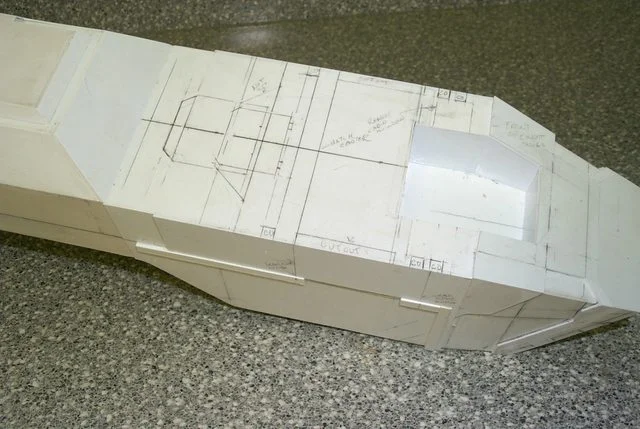
You can see that this is a very involved section.

ai.imgur.com_Olhacl.webp

The pieces of required substrate to the right and one of the edge pieces tacked onto the underside of top layer.

ai.imgur.com_kFUs5l.webp

Another view of the penciled in lines.

ai.imgur.com_Djvrdl.webp

And a front view for no particular reason.

E. Blackadder
 
There is a lot of confusion as to what I am trying to achieve regarding the top armour plating.

Well it's clear as mud to me and I wrote it. The thing is there are two layers to the armour; a 1.5 mm thick layer I call the substrate i.e. that which lies beneath the top layer and the 1.0 mm thick top sheet that I call the top layer. I want the top layer to be in one piece so I cut the substrate layer out of 5 pieces of 1.5 mm thick sheet styrene to be exactly the size of the top of the hull. Then I cut out the 1.0 mm armour sheet's side notches and the center opening for the fans because the 1.0 mm styrene is easier to cut exactly. Then I glued the five substrate pieces to the top armour sheet to make the requisite thickness of 2.5 mm. Now all that is left is to trim the remaining edges of the top sheet to the exact size of the completed substrate that is glued to the back of the 1.0 mm top sheet.

Mebe I should take a picture? :question:

It's hard to describe the procedure but suffice it to say here is the result.

ai.imgur.com_MZypwl.webp
The underside of the 1.0 mm top armour with the two 1.5 mm edge pieces installed and the three pieces of the base armour.

ai.imgur.com_epiCwl.webp
The topside of the 1.0 mm top armour showing the end of the edge pieces.

ai.imgur.com_Nd5dml.webp
The assembled top and base armour 2.5 mm thick with detail cutouts and edges dressed.

ai.imgur.com_mz5H2l.webp
Top view of the armour assembly.

ai.imgur.com_95rpel.webp
Edge on view of the top armour assembly.

--
E. Blackadder
 
ai.imgur.com_kNhPHl.webp
The moment of truth, does it fit?

ai.imgur.com_bsNlkl.webp
Seems like a good fit but too much flash.

ai.imgur.com_uapBYl.webp
Less flash more detail.

ai.imgur.com_TBKmVl.webp
The front edge needs trimming.

--
E. Blackadder
 
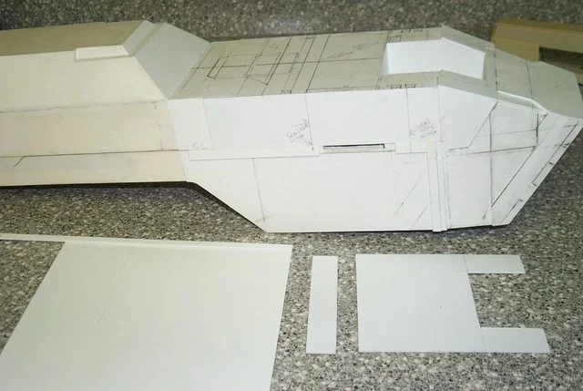
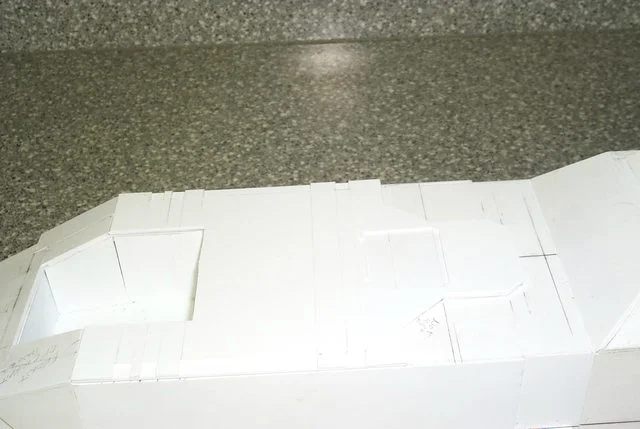
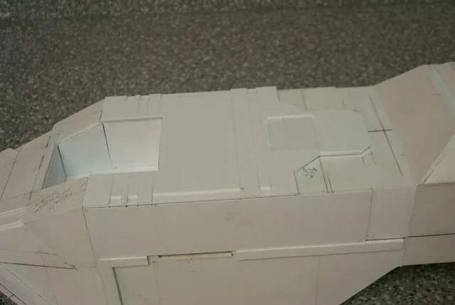
Not much to show for yesterday's work. The secondary layer of armour is attached, the cut outs on the side 90° corners have been dressed out with file and knife and sanded clean with fine sandpaper and file so the seams barely show. This is a downfall of many of the scratch built models I see, that the corners are not clean and crisp. No amount of greenstuff or filler will give that precise intersection and it is relatively easy to achieve with the proper knife and a good clean new 'single cut file'. I use a 'Nicholson' single cut with a coarse side and a fine side that also has one of the edges capable of cutting for a nice crisp interior 90° angle cut. Invest in a file card wire cleaner and clean your file regularly to keep the file teeth from clogging.

In all, the whole of the secondary armour is out of true by less than a quarter of a millimeter which is satisfactory to me and once it is rounded in the finally dressing that discrepancy will blend in I'm sure.

ai.imgur.com_Oao6Bl.webp
The right side is the master side I do all the planning on. Always use the same side for sketching and fitting pieces and don't shift your on model plan lines from right to left sides if you can help it or you will build in discrepancies that will make your work look lopsided.

ai.imgur.com_QbQqvl.webp
The left side pieces I cut using the right side pieces for a guide making allowances for penciled or scribed lines and dressing the two pieces to insure they precisely match one another. It's easier to do this before they are glued on than trying to correct them after they are installed.

ai.imgur.com_LJ1lZl.webp
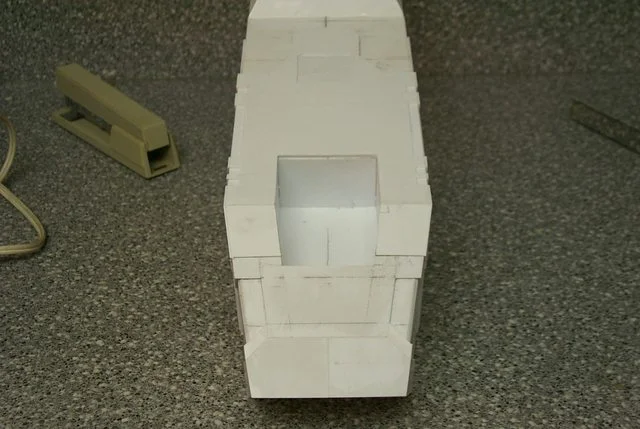
The front view appears satisfactorily symmetrical.

Now for the front cargo door.

--
E. Blackadder
 
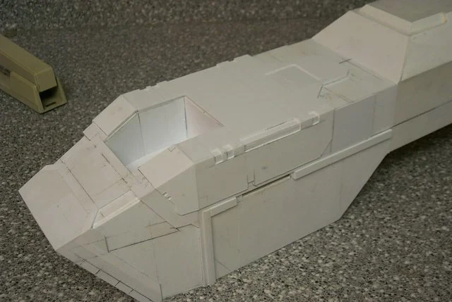
This was harder than one would suspect, not just cutting out rectangles in 5 mm thick plastic but the angles are actually rhomboid shape in the front elevation and set at compound angles to boot.

ai.imgur.com_NARCUl.webp

Also the 'bonnet' cover plate is installed.

ai.imgur.com_ULLl3l.webp

--
E. Blackadder
 
Sanai said:
You lost me at compound angles.
Looking great!

How do you think I felt and I built this into the model. A compound angle is a 3D angle and has more than one axis. a sophisticated miter saw can cut a two axis compound angle say north/south and up/down These notches have the original 90°cutout , plus the slope back of the cargo door,plus the angle inward of the hull opening bottom to top plus the flush front has to be flat. I count 4 spacial axises for each notch plus it's mirror counterpart on the other side, which transcends our normal three spacial dimension reality. We're talking Riemann space here......:D
E. Blackadder
 

About us

  • Our community has been around for many years and pride ourselves on offering unbiased, critical discussion among people of all different backgrounds. We are working every day to make sure our community is one of the best.

Quick Navigation

User Menu