Scratchbuilt Thunderhawk

  • The masquerade of murder returns! A new game of Vampires Amongst Us has begun. Unmask the killers, trust no one, and try to survive the night. Find out more and sign up now!
Lost time is not a consideration as I learn greatly from my mistakes and passing that information on to my loyal readers is the raison d'être of this thread.

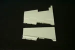
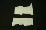
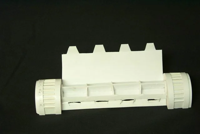
After much rebuilding and modification I seem to be on the right track regarding the wings. It is not too apparent in the photos but the leading edge of the wing tapers forward giving a nod to the necessity for an airfoil on a lifting surface. Of course the 'wing' (for lack of a better term) has all the aerodynamics of a truncated brick but that's the way the rendering looks.

ai.imgur.com_Wg7sOl.webp

http://i.imgur.com/Wg7sO

ai.imgur.com_L08g7l.webp

http://i.imgur.com/L08g7

Now I can proceed on the other wing.
 
I've never thought of these things flying as a result of proper aerodynamics anyway - It just seems like pure brute force. Put enough engines on it and you could get even that 'truncated brick' to fly...

This thread has always been a source of great fascination, inspiration and abject terror at the thought of trying anything approaching this myself! You never know... One day maybe. Keep it up.
 
Just so we maintain continuity I'll pick up from the last images I posted. I was about to start the left wing and the first order of business was to taper the leading edge to 4.5 mm in a cursory nod to an airfoil. This day I cut the indents in the leading edge, note the accompanying images:[attachment=1486][attachment=1487]
 

Attachments

  • 684.webp
    684.webp
    28.2 KB · Views: 66
  • 685.webp
    685.webp
    30.2 KB · Views: 76
As familiar as I am with current jet engines I'm stymied by the drum-like affairs surrounding the compressor housing and exhaust turbines on these engines. There are two above and two below and they seem to be vented with louvers fore and aft. My guess is they augment the intake air in the rarefied partial vacuum of orbital space but why they are needed on the rear as well is a mystery. After burner maybe?

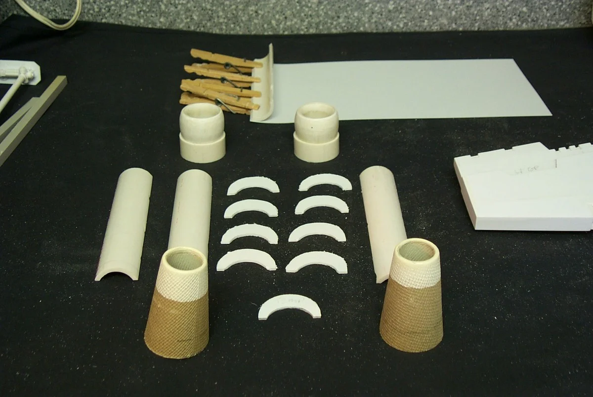
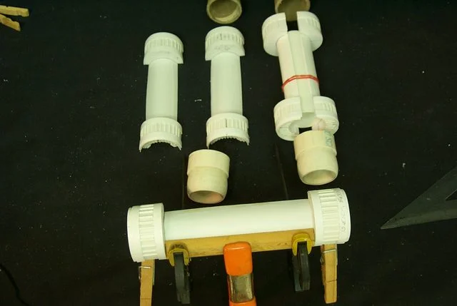
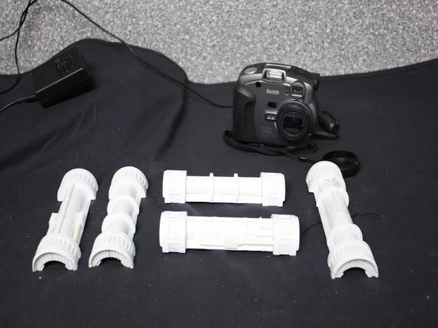
Anywho here are the bits components of the basic engine rough cut and ready for final shaping and assembly.

View attachment ai.imgur.com_7sKjo.jpg

ai.imgur.com_oCskQ.webp


ai.imgur.com_AnHC8.webp
 
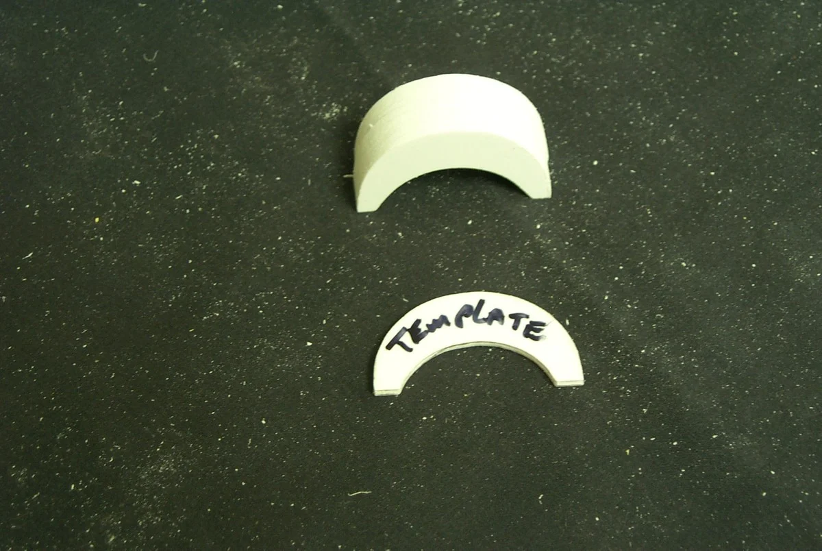
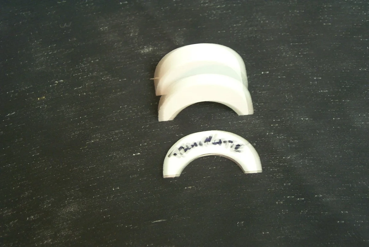
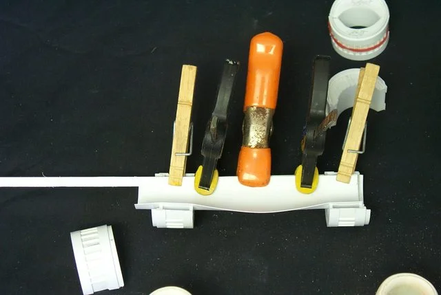
Taking the rough cut crescent pieces, I tacked them together with a couple of dots of ambroid and sanded them to the final shape. Then separating them more or less in the middle I reversed the two pieces to see how well they conform to their mirror inages. Then I compared the ends to the middle. Happily they matched up pretty good.

ai.imgur.com_7yJuv.webp


ai.imgur.com_vN1A4.webp


ai.imgur.com_5h7Yh.webp
 
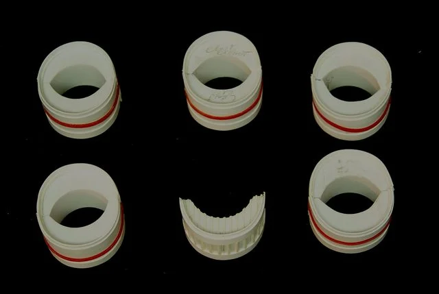
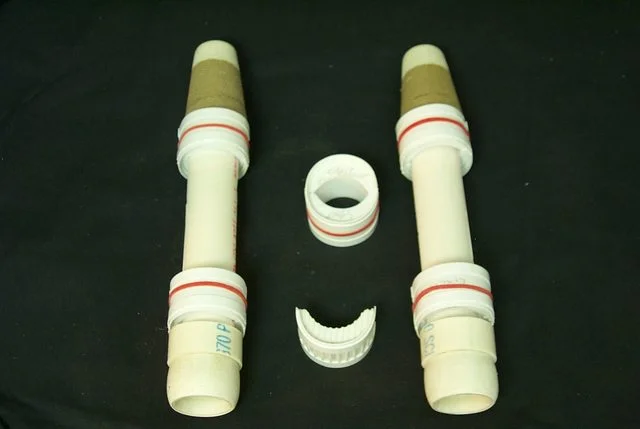
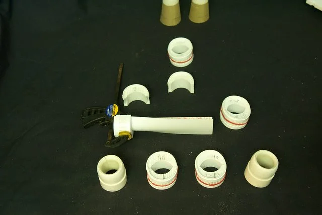
The whatever it is cowling for the engine basic construction. The first two I made just for practice and are 23 mm long and the base flairs slightly. They will be abbreviated and used on the belly engine. The next set will be for the wing engines now that I have the specs down and will be 22 mm in length.

ai.imgur.com_0OwBu.webp


ai.imgur.com_MGAFA.webp


ai.imgur.com_bpVYu.webp


Only eight more to do, I do so hate the repetition!
 
I have to say the FW engine plumbing looks more authentic. The 3D model has symmetrical plumbing fore and aft and top and bottom; it looks like he took a shortcut and just mirrored the detail. Not a big deal but not how a real engine looks plus there is no fuel control, accessory gearbox, generators or CSD's (Constant speed drives for the generators) and there is no bleed air for the pressurization and air conditioning.

Close as I am to the plumbing I'm going to have to find the FW engines and particularly the bottom view.

I have an excellent top view see the 4th image below.

ai.imgur.com_2psDpl.webp

http://i.imgur.com/2psDp.jpg[

ai.imgur.com_pPOwgl.webp

http://i.imgur.com/pPOwg.jpg

ai.imgur.com_e3JSjl.webp

http://i.imgur.com/e3JSj.jpg

View attachment ai.imgur.com_MUaA8l.jpg
http://i.imgur.com/MUaA8.jpg
 
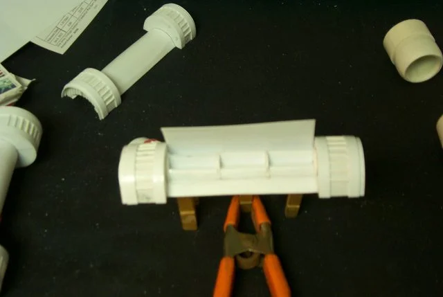
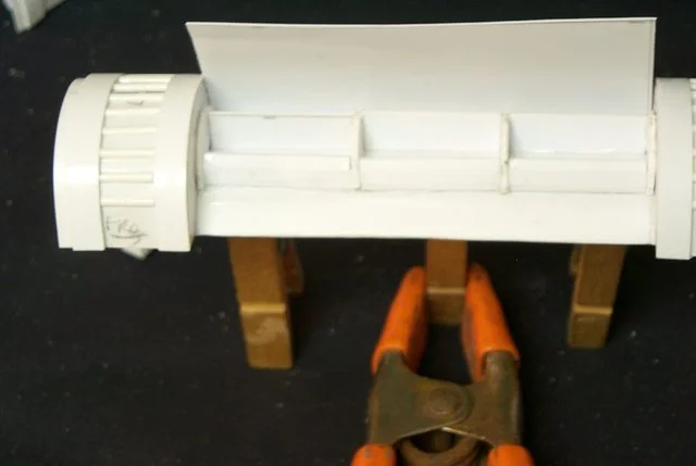
The #3 engine basic framework is complete and as usual it has set a standard that I will be hard pressed to equal. Everything came together so perfect than I could believe with less than a quarter mm error between the top and bottom halves and that will be covered by the fairing inboard of the engine so it won't be seen anyway

Now all that needs be do is to attempt to reasonably duplicate this on the other side.

ai.imgur.com_60V78l.webp

http://i.imgur.com/60V78.jpg

ai.imgur.com_OX5CPl.webp

http://i.imgur.com/OX5CP.jpg

ai.imgur.com_Ic8rGl.webp

http://i.imgur.com/Ic8rG.jpg

ai.imgur.com_4KqJSl.webp

http://i.imgur.com/4KqJS.jpg
 
Okay, the basic three engines are done now that all needs be done is the final sanding of the mating surfaces where they intersect the wing root and fair them into the wing. An added bonus is that the engines increase the overall wingspan by about 2.5 cm which alleviates my concern that the wings look too short. :D

Note that the center engine is longer than the wing engines; this is also true on the 3D drawings to make the exhaust housing come out. Can't be helped and I don't think it will detract from the overall look as the bottom of the hull is rarely seen anyway. I'm not sure how it looks on the FW model but the extra length of this model that gives it that more airworthy appearance necessitates strefching the engine. Makes it hell for engine changes though as two variations of engines must be stocked instead of one.

Seriously Blackadder, You're concerned with logistics now; Get a life!

ai.imgur.com_UTIk8l.webp

http://i.imgur.com/UTIk8.jpg

ai.imgur.com_esNfJl.webp

http://i.imgur.com/esNfJ.jpg
 
You gentle reader are about to reap the benefit of my stupidity. I went to great lengths to make the core housing of the engine as cylindrical as possible wasting hours in this fabrication. Recent images of the FW engine that have come into my possession have demonstrated to me that this effort while a worthwhile learning experience has been rendered superfluous. It seems there is another curved cowl sitting astride the core housing so I need to make another semi-cylinder of a lesser diameter and affix it to the core cylinder. What is left visible of the core cylinder could have been substituted with a nearly flat piece of stripping a centimeter wide.

View attachment ai.imgur.com_8bkgNl.jpg
http://i.imgur.com/8bkgN.jpg

ai.imgur.com_NkTcml.webp

http://i.imgur.com/NkTcm.jpg

ai.imgur.com_7UA5el.webp

http://i.imgur.com/7UA5e.jpg

Frustrating! HA!

Take that smarty pants Blackadder........
 
Well here it's the weekend again and everyone with a life is out enjoying it. Meanwhile I went ahead and detailed up an engine to see what it would look like. There are a few changes from either of the two versions I'm working from and I really wanted to use some of the hex rod I have lying about. so I made it into the fuel injector defuser. It doesn't look too bad and certainly different from the FW tube defuser in the same area. Of course the needs to be a lot more tiny bits to make it look like a real engine but nowheres near as complex as the SR71 engine pictured below................. No that way madness lies.

View attachment ai.imgur.com_uh8EMl.jpg
http://i.imgur.com/uh8EM.jpg
Outrageously complicated fuel control.

ai.imgur.com_PQnQsl.webp

http://i.imgur.com/PQnQs.jpg

ai.imgur.com_2ymYdl.webp

http://i.imgur.com/2ymYd.jpg

View attachment ai.imgur.com_BfJ8Bl.jpg
http://i.imgur.com/BfJ8B.jpg

View attachment ai.imgur.com_EtxJxl.jpg
http://i.imgur.com/EtxJx.jpg
Damn it's hard to believe that engine doesn't turn into a puddle of slag at that temperature!
 
Hey Blackadder!

I just wanted to say on behalf of everyone who follows this plog, your skills with plasticard are limitless and enviable. I know there is a lot of people who follow this log, myself included. In fact, I find myself getting quite excited whenever I've seen it updated. I just don't want you to think that our lack of replies is -because no-one is interested. I think we're just all stunned at your level of commitment, detail and ability.

Keep up the amazing work, you really are an inspiration to many!

u_m
 
[video=youtube]http://www.youtube.com/watch?v=KxLuShpaKrQ&feature=related[/video]

Those photo's made me think - someone built a real life Rhino, so why not a Thunderhawk...
(I can think of several reasons why but still...)

Why the hell not?
 
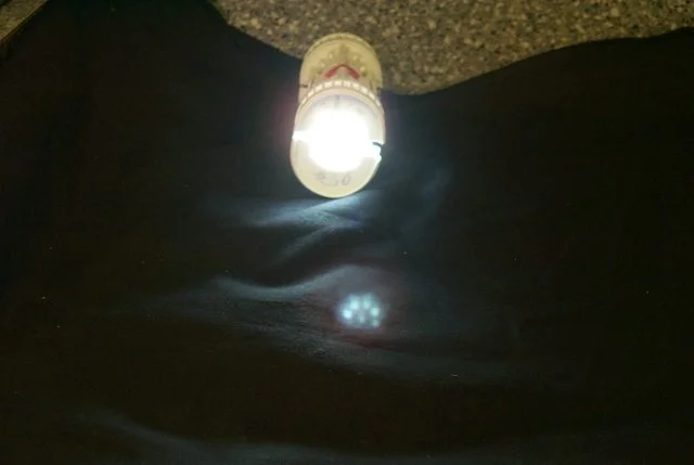
Resting on my laurels for far too long but I have not too much to show. I've been working on the engine detail and before I mount them I'd like to try to give them a bit of fire i.e. high intensity LED's. This is my first effort so be kind I only just slapped this together a few minutes ago.

View attachment ai.imgur.com_CWAV6l.jpg
http://i.imgur.com/CWAV6.jpg


ai.imgur.com_LISXZl.webp

http://i.imgur.com/LISXZ.jpg
 
For a moment when you said fire, I thought you were literally going to have fire coming out the exhausts knowing how far you go with these things :p
 
Okay, a while back someone asked me what Chapter colours I was going to paint this beauty (possibly not on this forum)? Well I hadn't considered that far down the line but I did receive some suggestions (Again maybe not from this forum) and I have decided barring a humongous meteorite strike or some other world shattering event I shall be going with this scheme. It just appeals to me adding just the right amount of racial senile decay and a patine of war weary resignation to the inevitable and ultimate end.

Whew, that is a depressing scenario if I do say so myself.

On a more upbeat note; the engines are just about done and I'll be posting an update soon.

With credit to the "Lord Inquisitioner" for the following images.

View attachment ai.imgur.com_Hk1Qrl.jpg
http://i.imgur.com/Hk1Qr.jpg
Now thats vomit green!

View attachment ai.imgur.com_lH9Pgl.jpg
http://i.imgur.com/lH9Pg.jpg
I really like this 3D rendering

View attachment ai.imgur.com_GAQYzl.jpg
http://i.imgur.com/GAQYz.jpg
I just hope my exhausts look this good

View attachment ai.imgur.com_dR9oPl.jpg
http://i.imgur.com/dR9oP.jpg
And my landing gear function this well.
 
Not much going on to this date I did some work on the lower portion of the engines and stated detailing the #3 engine upper half.

The biggest change is the following image which was the first taken with my new Rebel T3i Canon DSLR which Egad! is fully manual, I'm actually going to have to learn how to take pictures again. My old Kodak 290 (in the background) was having trouble extending the auto zoom lens (Getting it up as it were. ) so I guess it was time to retire it but this new camera will take some getting use to. I may have to read the manual though I did manage the image below right out of the box.

ai.imgur.com_rja78l.webp

http://i.imgur.com/rja78.jpg
 

About us

  • Our community has been around for many years and pride ourselves on offering unbiased, critical discussion among people of all different backgrounds. We are working every day to make sure our community is one of the best.

Quick Navigation

User Menu