


Scratchbuilt Thunderhawk
- Thread starter The_Blackadder
- Start date
-
The masquerade of murder returns! A new game of Vampires Amongst Us has begun. Unmask the killers, trust no one, and try to survive the night. Find out more and sign up now!
You are using an out of date browser. It may not display this or other websites correctly.
You should upgrade or use an alternative browser.
You should upgrade or use an alternative browser.

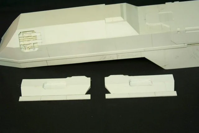
Department of one step forward and two back. Discovered an error in my building of the air brake panel recess. Had to tear it out and redo it. Two days and I'm back to where I was two days ago. but the cavity looks a lot better and that's what counts.
The slightly insane Blackadder

Note that the recess is now lined with 0.10 x 0.250 inch strips and the inner wall echoes the outer shape of the superstructure. You don't? well no one else would have either and I just pissed away my time rebuilding that which no one would have noticed anyway.
--
E. Blackadder
The slightly insane Blackadder
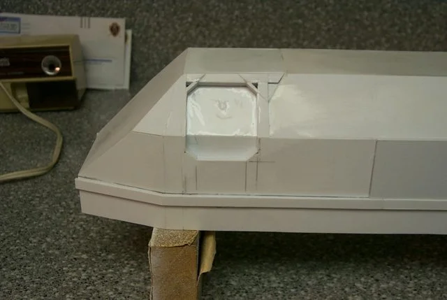
Note that the recess is now lined with 0.10 x 0.250 inch strips and the inner wall echoes the outer shape of the superstructure. You don't? well no one else would have either and I just pissed away my time rebuilding that which no one would have noticed anyway.
--
E. Blackadder
Another peek into the skunk works. Out of this hodge podge of scribbles I hope to extract a semblance of order and replicate the internal plumbing.
I hope I have enough scrap tubing.
--
E. Blackadder
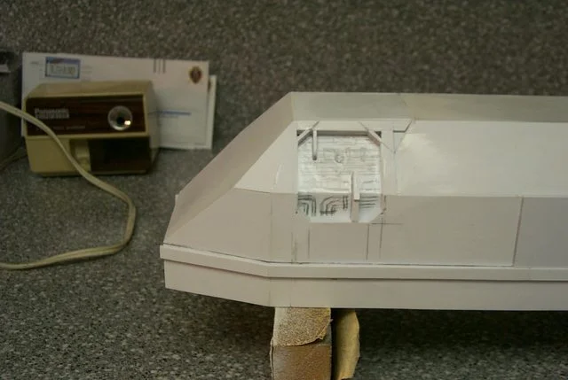
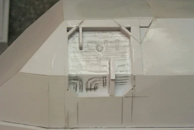
I hope I have enough scrap tubing.
--
E. Blackadder
The plumbing installed, a lot of pipes for such a small area. I suppose fuel lines and tubes for air conditioning and pressurization. Too high for lavatory waste pipes.
The right side:
And the left side:
E. Blackadder
The right side:

And the left side:

E. Blackadder
Enough resting on my laurels; there's nothing difficult about this detailing.
The thin pipe is actually made from old plastic flower pot hangers. you know the kind that have the hook moulded into them. I saved a bunch of them years ago and I'm soon going to be running out.
I used styrene rods for the bending and bent them with a pair of needlenose pliers. The trick is for more leverage to bend the rod before you cut it. Then over bent the angle and flex it back to the angle you want. Styrene fatigues quickly and should hold it's bend when glued in place.
Here's a short tutorial on pipe fitting.
The simplest is to just cut rings in the next size larger of the Evergreen telescoping tubing. Slide the ring onto the smaller rod or tube and glue in place with ProWeld thin cement. No need for pictures of this process, But.......
sometimes you want a really thin sleeve on your tubing.
First file or sand the smaller dia. tube to a tapered end:
Then with a thin pointed Xacto blade ream out the larger dia. tube:
to receive the previously tapered rod or tube:
Join the two tubes and cement and set aside to dry on a flat surface:
Next; Really thin bands on the tubing.
--
E. Blackadder
The thin pipe is actually made from old plastic flower pot hangers. you know the kind that have the hook moulded into them. I saved a bunch of them years ago and I'm soon going to be running out.
I used styrene rods for the bending and bent them with a pair of needlenose pliers. The trick is for more leverage to bend the rod before you cut it. Then over bent the angle and flex it back to the angle you want. Styrene fatigues quickly and should hold it's bend when glued in place.
Here's a short tutorial on pipe fitting.
The simplest is to just cut rings in the next size larger of the Evergreen telescoping tubing. Slide the ring onto the smaller rod or tube and glue in place with ProWeld thin cement. No need for pictures of this process, But.......
sometimes you want a really thin sleeve on your tubing.
First file or sand the smaller dia. tube to a tapered end:

Then with a thin pointed Xacto blade ream out the larger dia. tube:
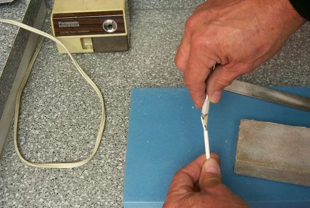
to receive the previously tapered rod or tube:
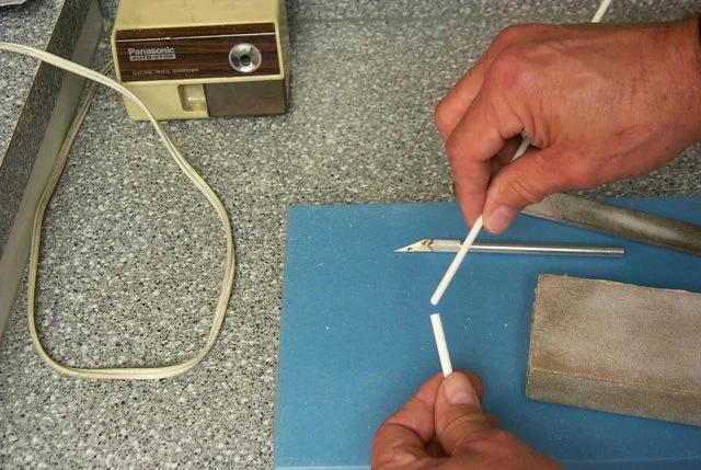
Join the two tubes and cement and set aside to dry on a flat surface:

Next; Really thin bands on the tubing.
--
E. Blackadder
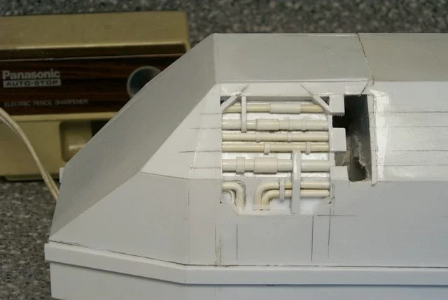
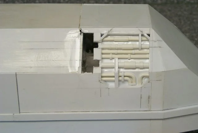
Cutting out the hull was the hard part, another step backwards but it had to be done. A 2 mm bulkhead to strengthen the casement and
to provide a secure mount for the hinge assembly. the cutting out the hinge recesses which gives me this result and no significant damage.
--
E. Blackadder
to provide a secure mount for the hinge assembly. the cutting out the hinge recesses which gives me this result and no significant damage.
--
E. Blackadder
Below is a composite image of the left side hinge showing the range of motion and the assembled components. Now all I have to do is reproduce it for the right side. I'll take pictures of the components seperately for the right side hinge; I didn't for the left because I wasn't sure the damned thing would work. 
--
E. Blackadder

--
E. Blackadder

Dude...those pipes look amazing. I love the effect you've achieved with them. And the method you used is so simple...it makes me wish I played Space Marines so that I could put some exposed cooling pipes onto my vehicles. 
There's nothing difficult about this detailing.
The thin pipe is actually made from old plastic flower pot hangers. you know the kind that have the hook moulded into them. I saved a bunch of them years ago and I'm soon going to be running out.
I used styrene rods for the bending and bent them with a pair of needlenose pliers. The trick is for more leverage to bend the rod before you cut it. Then over bent the angle and flex it back to the angle you want. Styrene fatigues quickly and should hold it's bend when glued in place.
Here's a short tutorial on pipe fitting.
The simplest is to just cut rings in the next size larger of the Evergreen telescoping tubing. Slide the ring onto the smaller rod or tube and glue in place with ProWeld thin cement. No need for pictures of this process, But.......
sometimes you want a really thin sleeve on your tubing.
First file or sand the smaller dia. tube to a tapered end:
Then with a thin pointed Xacto blade ream out the larger dia. tube:
to receive the previously tapered rod or tube:
Join the two tubes and cement and set aside to dry on a flat surface:
Back to the hinges:
The hinge installed shown in the closed position:
The hinge in the open position:
Sink me, it works!
I'll be finishing skinning the fuselage this weekend.
The thin pipe is actually made from old plastic flower pot hangers. you know the kind that have the hook moulded into them. I saved a bunch of them years ago and I'm soon going to be running out.
I used styrene rods for the bending and bent them with a pair of needlenose pliers. The trick is for more leverage to bend the rod before you cut it. Then over bent the angle and flex it back to the angle you want. Styrene fatigues quickly and should hold it's bend when glued in place.
Here's a short tutorial on pipe fitting.
The simplest is to just cut rings in the next size larger of the Evergreen telescoping tubing. Slide the ring onto the smaller rod or tube and glue in place with ProWeld thin cement. No need for pictures of this process, But.......
sometimes you want a really thin sleeve on your tubing.
First file or sand the smaller dia. tube to a tapered end:
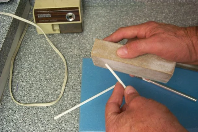
Then with a thin pointed Xacto blade ream out the larger dia. tube:

to receive the previously tapered rod or tube:
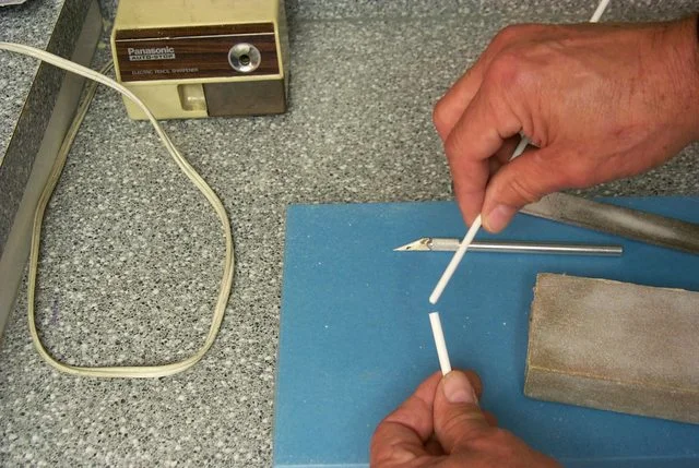
Join the two tubes and cement and set aside to dry on a flat surface:
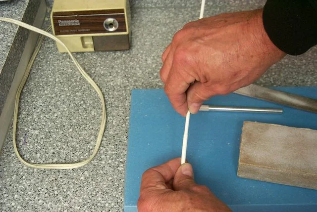
Back to the hinges:
The hinge installed shown in the closed position:

The hinge in the open position:

Sink me, it works!
I'll be finishing skinning the fuselage this weekend.
I wouldn't have thought that such a seemingly simple moving device could have consumed so much time but at last it is done except for the door panels. I managed to sheath the lower hull and around the brake openings on both sides; not too far behind my expectations for the weekend in spite of having to work a bit.
Rather pleased at the symmetry and the very close match of the left side and right side structures:
The open position, a tad larger than the 3D image but it's a moving part.
--
E. Blackadder
Rather pleased at the symmetry and the very close match of the left side and right side structures:
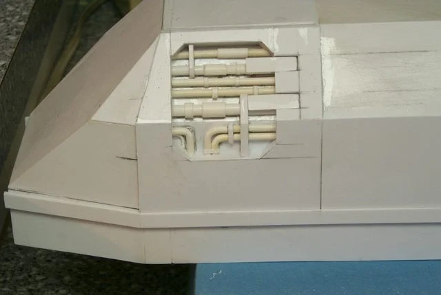
The open position, a tad larger than the 3D image but it's a moving part.

--
E. Blackadder
I've been neglecting my public with some personal issues and dressing some of the top hamper that doesn't make for interesting updates. But now there is some progress on the underbelly where I am designing the landing pad wells.
First, the crude sketches:
First, the crude sketches:


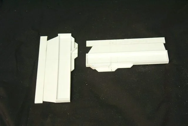
The wing root mount plate and engine mount tab outboard with one piece temporarily tacked in place to demo the approximate position. I think it's too far forward but that is the beauty of modular construction for once they are assembled I can place them where ever they appear correct.

The landing gear wells are coming along quite nicely. I've had a thought to build each wing separate from the hull and mount them with screws for easy disassembly for transport. This will be quite a large model and damage will occur if in one piece.
http://i.imgur.com/tpPDe.jpg
http://i.imgur.com/tpPDe.jpg
The gear well and landing pads scale = 13 ft X 7 ft per pad or 4 meters X 2 meters if you like. We now begin the excursion into attempting to build the retraction mechanism.
http://i.imgur.com/xOCGi

http://i.imgur.com/xOCGi
The gear well skin surface covered with the actual model for reference.
http://i.imgur.com/K4MPm.jpg
http://i.imgur.com/QQn5v.jpg
Now in most of the images I have seen the gear is canted outboard. This will pose a problem as the centering strut ( That which keeps the gear aligned with the direction of flight/landing) will have to pivot as the gear raises or lowers. This posed no problem for FW as their gear doesn't move but it appears unique in my experience with aircraft unless the gear folds out from the centerline in the manner of say a Boeing 727. The problem is that the main strut descends vertically down so the centering 'down and locked strut' jams on deployment. A pretty pickle of a problem.
Also the 'Down and lock' strut has no where to go when the gear is retracted; Ha! What's up with that???? FW really dropped the ball on this; engineeringwise.
IMCO
--
E. Blackadder
Quit 'cher bellyach'n Blackadder and stop make'n excuses!
http://i.imgur.com/K4MPm.jpg

http://i.imgur.com/QQn5v.jpg
Now in most of the images I have seen the gear is canted outboard. This will pose a problem as the centering strut ( That which keeps the gear aligned with the direction of flight/landing) will have to pivot as the gear raises or lowers. This posed no problem for FW as their gear doesn't move but it appears unique in my experience with aircraft unless the gear folds out from the centerline in the manner of say a Boeing 727. The problem is that the main strut descends vertically down so the centering 'down and locked strut' jams on deployment. A pretty pickle of a problem.
Also the 'Down and lock' strut has no where to go when the gear is retracted; Ha! What's up with that???? FW really dropped the ball on this; engineeringwise.
IMCO
--
E. Blackadder
Quit 'cher bellyach'n Blackadder and stop make'n excuses!
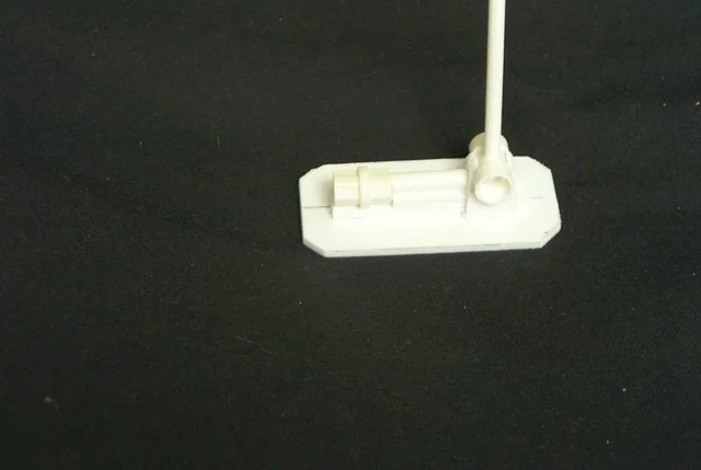
The resolution of the foot pad is pretty pitiful but this is what I gleaned from it.
http://i.imgur.com/xOrIU.jpg
http://i.imgur.com/W2i3Q.jpg
http://i.imgur.com/xOrIU.jpg

http://i.imgur.com/W2i3Q.jpg
The gear temporarily installed in gear wells to check for clearance and operating space. There appears to be sufficient room and the struts remain within the hull instead of poking out through the wing root whew!
http://i.imgur.com/lWAZP
(http://i.imgur.com/03w7w
--
E. Blackadder
whew! 
http://i.imgur.com/lWAZP

(http://i.imgur.com/03w7w
--
E. Blackadder
ARMORMAN said:Found some shots of the landing gear and bays of the FW resin kit:
http://www.flickr.com/photos/8476775@N05/2596192384
http://www.flickr.com/photos/8476775@N05/2596192018
Whoa those are some fantastic shots, much better than anything I have. Very much appreciated; I am in your debt.
Viewing these it very much reinforces what I have suspected all along; FW got the main gear retraction all wrong.
As the forward (angled) retract cylinder contracts it pivots the main strut forward. the landing pad with what I assume is a leveling cylinder collapses forward with the main strut intersecting with the hull well forward of the gear well opening instead of covering it forming a door as FW intends.
My main strut perforce will collapse vertically and the angled retract cylinder will be more of a stabilizing/centering device to keep the gear from swiveling.
The whole hydraulic/mechanical structure from an engineering standpoint is totally inadequate for a vehicle the size of the T'hawk but at least my interpretation will keep the external configuration intact with the gear retracted.
The forward strut is a different case and I may be able to adapt the FW design by placing the foot pad further aft on the shock strut the short strut/pad may intersect the hull where FW intended when retracted and cover the well.
The Blackadder, I'm not an engineer but I play one on the internet
--
E. Blackadder
I'm trying to build the wings as light as possible because I want the upper wing appendages with the lascannons on the tips to be movable and not be a truss for the support of the lower main wing as in the FW model. FW really ought to research into drilling and tapping threads into resin and installing machine screws to hold the heavier pieces together. Crazy glue and even epoxy sometimes just isn't enough.
When I get to mounting the wings on the hull I'll do a tutorial on screwing.
Not what you're thinking,
Blackadder
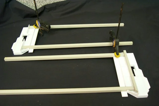
Back when I was building Lucie I bought some gray ABS plastic box beam tubing manufactured by Plastruct. I don't recommend using this stuff but I've got to get rid of it.so I'm using it to frame the engine mounts and the wing core assembly. It's stronger than styrene but doesn't cement well with styrene glue unless you rough the surface up with sandpaper. Or you could use ABS cement which I believe is mainly acetone.
http://i.imgur.com/3ydfP
http://i.imgur.com/TPmC6
Before you get your 'nads in a knot the just installed beams will be cut very short; they're just left long for now to insure they are parallel. That is a building hint; it's easier to insure frames are parallel and true if they are long than short. The discrepancy in trueness is easier to detect with the longer length.
When I get to mounting the wings on the hull I'll do a tutorial on screwing.
Not what you're thinking,
Blackadder
Back when I was building Lucie I bought some gray ABS plastic box beam tubing manufactured by Plastruct. I don't recommend using this stuff but I've got to get rid of it.so I'm using it to frame the engine mounts and the wing core assembly. It's stronger than styrene but doesn't cement well with styrene glue unless you rough the surface up with sandpaper. Or you could use ABS cement which I believe is mainly acetone.
http://i.imgur.com/3ydfP

http://i.imgur.com/TPmC6
Before you get your 'nads in a knot the just installed beams will be cut very short; they're just left long for now to insure they are parallel. That is a building hint; it's easier to insure frames are parallel and true if they are long than short. The discrepancy in trueness is easier to detect with the longer length.
We're starting at the ground floor building the wings so there shouldn't be any question later on how it was done. Now if I can just do it without a mistake.
http://i.imgur.com/ZDVp7
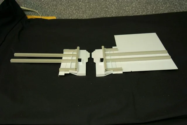
I calculated the wing outboard of the engine should extend 17.5 mm excluding the wing tip armament That seems a bit small to me but figures don't lie. We'll just have to see I can always make them bigger.
http://i.imgur.com/ZDVp7
I calculated the wing outboard of the engine should extend 17.5 mm excluding the wing tip armament That seems a bit small to me but figures don't lie. We'll just have to see I can always make them bigger.
Thunderhawks have always had slightly short/stubby wings, which is kinda part of their look. (Most Marine flyers, like the stormraven and landspeeders share this trait)
Thanks for the reply,
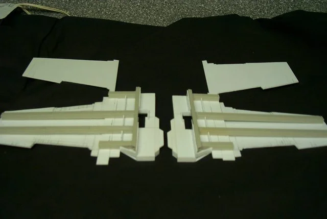
The wing core plates in 2.0 MM styrene cut out and ready for install.
http://i.imgur.com/3H6Ul
http://i.imgur.com/NAmz
The wing core plates in 2.0 MM styrene cut out and ready for install.

http://i.imgur.com/3H6Ul
http://i.imgur.com/NAmz
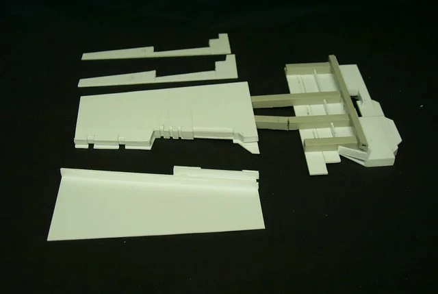
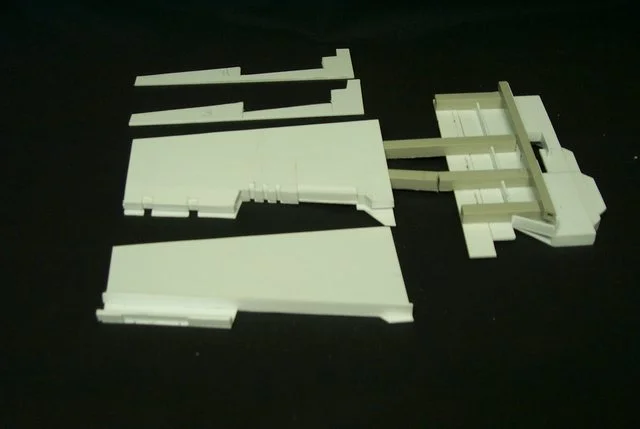
I'm afraid you gentlemen and mayhaps ladies perhaps have hitched your wagon to a falling star. I wasted a week on a futile bit of building that did not pan out. Going back to square one I have in a flurry of desperation managed to come up with a better way of doing the wings. This morning I started gluing the first wing together and the foreground piece is the second wing which I hope will be more facile to build now that I think I know what I am doing.
http://i.imgur.com/T15nG
http://i.imgur.com/FNTlE
The extremely fallible Blackadder
http://i.imgur.com/T15nG
http://i.imgur.com/FNTlE
The extremely fallible Blackadder
Keep up the good work, though I may not reply often, I have been, and continue to, read every post you make on this the day you make the post. You have put so much effort into this, you should carry it through to its conclusion. You really oughta consider starting a bussiness or doing comission work or applying for a job somewhere, you are pretty damn talented.